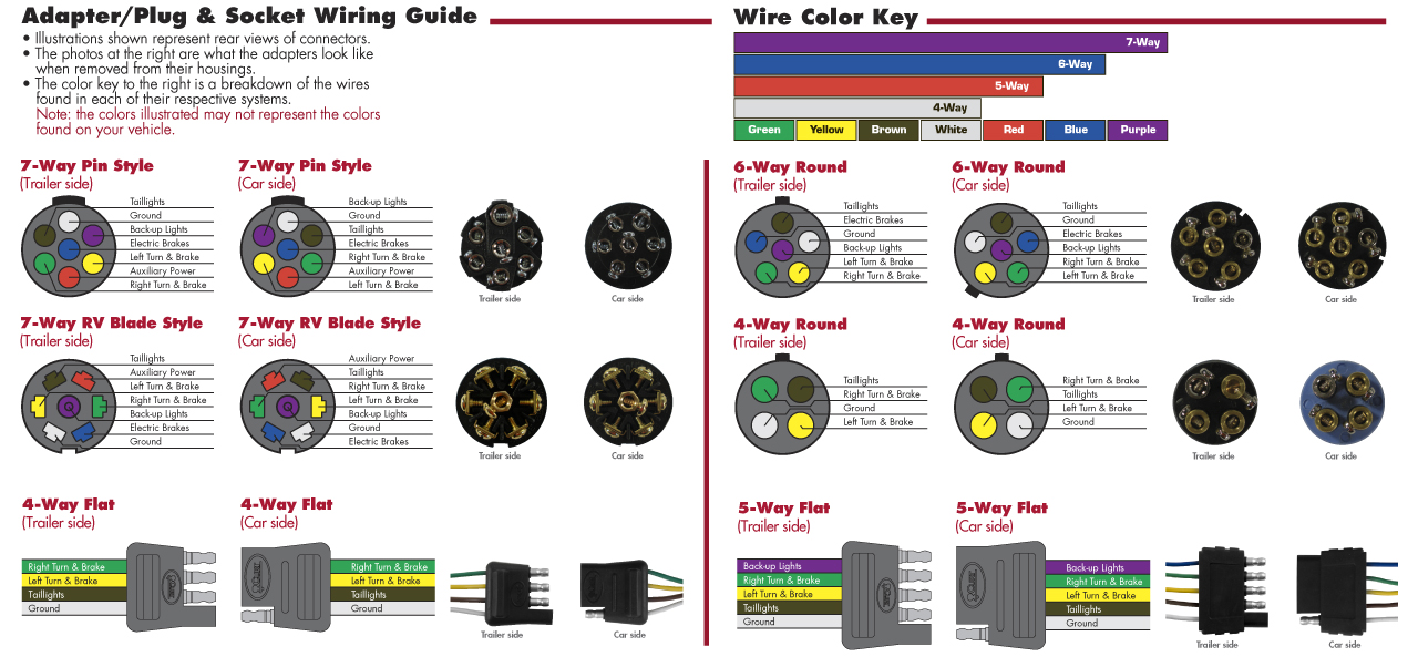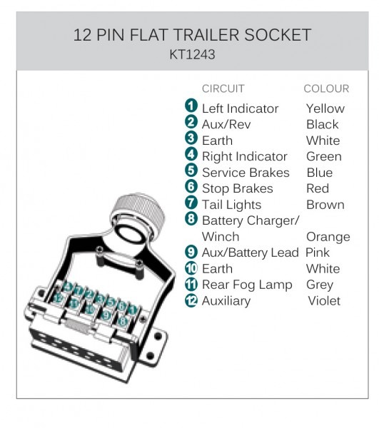
#TRAILER PLUGS DIAGRAMS ISO#
The problematic part here is that pin 5 is used for trailer brake which means that if you for some reason connect an Australian trailer to a towing vehicle with ISO wiring you will get into trouble with the trailer brakes being applied as soon as you turn on the lights. (Vehicle wired for +12V, permanent or via ignition and trailer wired for fog lamps)Īustralia uses basically the same wiring with the exception for pin 5 and pin 2. This is why in regions using this connector, trailers on the road are occasionally seen with the rear fog lights on when they should be off.

Later pin 2 (54G) has been used for a variety of functions different from the original intent.
#TRAILER PLUGS DIAGRAMS REGISTRATION#
Tail lights, clearance lights/outline marker lights and registration plate light left sideĪccording to DIN 72552 pin 54G was initially intended for electrical control of brakes on trailers. Tail lights, clearance lights/outline marker lights and registration plate light right side Joining the pins for right and left tail lights (58R and 58L) can cause problems on German cars where it is possible to activate Standing Lamps on only one side of the vehicle. In these cases exclude connection for right tail light (58R) and rear fog light (54G) and connect the tail lights only to pin for left tail light (58L). On older trailers there's sometimes a 5-wire setup using a 7-pin connector. The 7-pin connector uses on newer trailers all 7 pins according to the ISO standard. Physical design according to standard ISO 1724. The following supplementary information exists for the connector:ħ-pin ISO 1724 trailer connector type 12N (Towing vehicle side) Reversing lamps, control current to block surge brakes when reversing. Tail lamps, clearance lamps/outline marker lamps and registration plate lamp left side Tail lamps, clearance lamps/outline marker lamps and registration plate lamp right side Physical design of the standard ISO 11446 but also called Jaeger-connector from the company that developed it. The color coding is defined in ISO 4141-3, but the standard color codes are not always followed and may be different for a particular vehicle.ġ3-pin trailer connector ( ISO 11446) Heavy trucks that may have 12V systems are usually older (vintage vehicles) or on non-European markets. Vehicles and trailers with 6V systems can use the 7-pin or a 5-pin connector, but these are rare today.

Exceptions for the 7-pin connector may exist where they may be used for 6V and 24V. The connectors are designed for 12V systems. The 13-pin version being phased in is newer, provides more services than the 7-pin, a more positive locking and also better protection against moisture and contamination. In Europe, both 7-pin (ISO 1724) and 13-pin (ISO 11446) are common. Trailer connectors between the trailer and passenger car, light truck or heavy trucks with 12V systems These are listed below, with notes on significant deviations from them that can cause problems. A number of ISO standards cover trailer connectors, the electrical connectors between vehicles and the trailers they tow that provide a means of control for the trailers.


 0 kommentar(er)
